This video includes audio as well.
Tuesday, August 25, 2009
Thursday, August 20, 2009
CAD MidWest 2009 - September 22
Every year Mid-West CAD hosts a technology expo at Unity Villiage in Kansas City, MO. This year our event takes place on September 22 and you won't want to miss it!
Lucy Kuhns from Autodesk will be on-hand to answer questions and lead some Civil 3D sessions. If you're in the area or want to come to the KC area, you can sign up for CAD MidWest by following this link. I hope to see you there!
www.mwcad.com/cadmidwest.pdf or, you can sign up through Autodesk here.
Oh, and if you're not familiar with Lucy you can search Google or Bing to find out more. If you're wanting to become a Civil 3D power-user, you should check her out, Lucy is one of the best.
See ya,
Denver
Wednesday, August 12, 2009
Vista 64 SP2 Broke Civil 3D...
Update: I didn't get a chance to see what was wrong with Civil 3D 2009. Windows 7 came....
Hey guys - somehow SP2 for Vista x64 was installed last night and this morning, Civil 3D 2010 and 2009 are looking for .dll files! I've specified not to install the service pack and it's been sitting in my Windows Updates - Updates to Install list for about a month. So it was a surprise to me when I booted up and got the "Windows is Configuring Updates" balloon.
To fix it, I've done a quick reinstall of both apps and 2010 seems to work okay but 2009 is still giving me fatal errors. AutoCAD 2010 and 2009 seemed to work just fine without reinstalling.
By quick reinstall I mean;
- Insert the Disk (if installed from disk)
- Close the initial setup screen
- Go to Programs and Features
- Right-click on application and pick Uninstall/Change
- Pick Reinstall from the wizard
- Wait it out
I will update this post when I figure out what is wrong with Civil 3D 2009!
See ya,
Denver
Sunday, August 2, 2009
Civil 3D 2010 Update 1 Available
Autodesk released Civil 3D 2010 Update 1 on Friday. You can download it from the links below:
AutoCAD Civil 3D 2010
AutoCAD Civil 2010
Plenty of fixes in the update so if you're using 2010, you should download and install. I've downloaded and installed without any problems... so far. I'll update this post if I am made aware of any negative effects.
See ya,
Denver
AutoCAD Civil 3D 2010
AutoCAD Civil 2010
Plenty of fixes in the update so if you're using 2010, you should download and install. I've downloaded and installed without any problems... so far. I'll update this post if I am made aware of any negative effects.
See ya,
Denver
Saturday, July 25, 2009
Civil 3D 2010: Right-of-Ways in Section View
This one has audio, speakers or headphones required!
See ya,
Denver
See ya,
Denver
Friday, July 17, 2009
Monday, July 13, 2009
Using a Custom Template
In AutoCAD or Civil 3D, you may want to use a custom template. I've outlined it in this PDF file. It's pretty quick and dirty.
See Ya,
Denver
See Ya,
Denver
Wednesday, July 1, 2009
Selection Sets
Civil 3D offers a command called Select Similar. If you right-click in the drawing area after selecting an object, select similar will appear at the bottom of the short cut menu.
This is a command that will come in very handy when working with Civil 3D. A few examples;
When deleting section views, pick one of the section view graphs, right-click, pick Select Similar and then all of the views are selected. This way, you won't erase your sections, only the views from the drawing.
If you have a bunch of linework to select, pick one of each, line, circle, arc, polyline, ect., then you can right-click and pick Select Similar and all of the linework is selected.
Sample Lines.... pick one, then right-click and pick Select Similar, all of the sample lines are selected.
Anyway, hopefully you get the point. This can save time and it's only available in Civil 3D. AutoCAD doesn't have such a command yet.
Stay productive!
See ya,
Denver
Friday, May 29, 2009
Blog Chat
UPDATE: I've removed Civil Chat from the blog due to lack of use.
I've added a chat applet on the sidebar to the right. If it says DenverG is Available, then I'm logged on and can chat. If you have a quick question or just want to say hey. You can do so anonymously or you can enter a personal chat name. Hope to talk to some of you soon!
See ya,
Denver
I've added a chat applet on the sidebar to the right. If it says DenverG is Available, then I'm logged on and can chat. If you have a quick question or just want to say hey. You can do so anonymously or you can enter a personal chat name. Hope to talk to some of you soon!
See ya,
Denver
Wednesday, May 27, 2009
Autodesk Service Packs - EXE to MSP
I've wondered for a while why Autodesk posts it's service packs in only EXE format. If you've ever wanted to deploy Autodesk software with the service pack tied in, you know about this little conversion that needs to happen before the deployment will accept.
When you download a service pack from Autodesk you can save it an install it without doing anything as long as you're applying the patch to a stand-alone copy. To apply the patch to a deployment, you need a MSP file. Here's how you do it:
1. Start the Windows Command Prompt (DOS Window)
2. Navigate to the directory where the patch resides. (I'll use C:\Temp for this example)
3. Enter the patch name followed by /e and then an output path for the MSP file.
Example: (patch name is C3DSP1.exe)
C:\temp\c3dsp1.exe /e c:\temp\msp\c3dsp1.msp
The example above takes the .exe file from the temp directory and extracts the msp file into the temp/msp folder.
4. You can now move the MSP file, if needed, to a location that can be accessed by the deployment.
Good Luck with those deployments!
See ya,
Denver
Friday, May 22, 2009
Creating AutoCAD Linetypes
A friend and mentor of mine, Jerry Bartels from Autodesk has recently posted a video on his YouTube channel that describes how to create linetypes in AutoCAD. He's doing the work in Civil 3D, but using the Express Tools that ship with AutoCAD as well. It's a great video, so you might want to check it out.
That led me to think of other ways to create linetypes and as I was cleaning out my overpopulated "in/out" box in my office, I came across a piece of paper that I've had for many years describing how to open up notepad and generate a linetype file that AutoCAD will read. I thought that I would just get rid of the paper since it's old and newer, quicker ways of linetype generation are available. Then I thought, maybe I'll put it on my blog, so here we are. After I transcribe this, I'll finally be able to get rid of that paper that has been following me around for years!
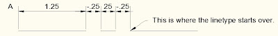
If you open the ACAD.LIN file that ships with AutoCAD, you'll see all of the linetype descriptions and their definitions. This is a general linetype you will see in ACAD.LIN;
*CENTER,Center ____ _ ____ _ ____ _ ____ _ ____ _ ____
A,1.25,-.25,.25,-.25
The top line always starts with an astrik followed by the name of the linteype. The description is next, seperated from the name with a comma. After the description, a preview of the linetype is shown.
The bottom line is the linetype definition. The definition always begins with a capitol A. Next is the length of the first dash (1.25). AutoCAD linetypes must start with a dash. There is no way around it. Next is the location of smaller dash from the left side of the longer dash (-.25). Next is the length of the smaller dash (.25). The last value is the location of the smaller dash from the right side of the longer dash (-.25). All of those different values are seperated with a comma.
That led me to think of other ways to create linetypes and as I was cleaning out my overpopulated "in/out" box in my office, I came across a piece of paper that I've had for many years describing how to open up notepad and generate a linetype file that AutoCAD will read. I thought that I would just get rid of the paper since it's old and newer, quicker ways of linetype generation are available. Then I thought, maybe I'll put it on my blog, so here we are. After I transcribe this, I'll finally be able to get rid of that paper that has been following me around for years!
If you open the ACAD.LIN file that ships with AutoCAD, you'll see all of the linetype descriptions and their definitions. This is a general linetype you will see in ACAD.LIN;
*CENTER,Center ____ _ ____ _ ____ _ ____ _ ____ _ ____
A,1.25,-.25,.25,-.25
The top line always starts with an astrik followed by the name of the linteype. The description is next, seperated from the name with a comma. After the description, a preview of the linetype is shown.
The bottom line is the linetype definition. The definition always begins with a capitol A. Next is the length of the first dash (1.25). AutoCAD linetypes must start with a dash. There is no way around it. Next is the location of smaller dash from the left side of the longer dash (-.25). Next is the length of the smaller dash (.25). The last value is the location of the smaller dash from the right side of the longer dash (-.25). All of those different values are seperated with a comma.
That is a simple linetype definition. What if you need to add text or symbols to your linetype? Easy enough, let's take a look.
*GAS_LINE,Gas line ----GAS----GAS----GAS----GAS----GAS----GAS--A,.5,-.2,["GAS",STANDARD,S=.1,R=0.0,X=-0.1,Y=-.05],-.25
There are a few more items to consider within the definition above. The top line is the same and the beginning of the bottom line is the same. First the A. Then the length of the first dash. Then the distance of the text from the left side of the first dash. Then, within the brackets, the text to be shown is listed in quotes followed by the text style ("GAS",Standard). The S= stands for Size of Text, followed by the text size value (S=.1). Then R= (Rotation) followed by the rotation value (R=0.0). Then X= (Location of text from the right side of the dash) followed by the value (X=-.05). Then Y= (Location of the text above or below the dash) followed by the value (Y=-.05). If a negative value is used, the text is moved down, below the dash. This rounds out the bracket text. The final value is the location of the text from the right side of the dash (-.25). Again, this is all seperated by commas.
I don't know that there is enough space to get a full drawing description like I've pasted below the simple linetype. You can download a PDF of these linetype instructions here.
There are a number of options for creating linetypes within AutoCAD. This is just one of them, and it's the long (old) way at that!
See ya,
Denver
Friday, May 1, 2009
2010 Civil Product Links
I thought I'd post some links for downloads on 2010 products.
For the AutoCAD Civil and Civil 3D 2009 patch that allows those two versions to use Autodesk Vault 2010, click here.
For the AutoCAD Civil and Civil 3D 2010 System Requirements, click here.
For all other updates for AutoCAD Civil and Civil 3D 2010, click here.
That should do it, all links to the Autodesk website.
See ya,
Denver
Friday, April 24, 2009
New Releases, New Features, Old Habits
Another release of AutoCAD always brings about uncertainty, doubt, and a lot of questions. There are firms who will adopt the new release and firms who haven't adopted a new release in 10 years. Out of all the questions I get when visiting with clients around release time is; "why does Autodesk release a new version of AutoCAD every year?" There are a hundred correct answers to that question. There are stock holders to keep happy, employees to pay, and all of the things that go along with operating a worldwide – publicly traded company. But on the other side of that coin is technology. Like it or not, technology drives our business, whether that business is civil engineering, architectural design, or the broad scope that is mechanical engineering; technology surrounds your every decision.
Take civil engineering for example. Current technology dictates what type of manhole is used in residential sub-divisions and erosion technology dictates how a site will be prepped and re-designed. These scenarios change over time – because technology changes. I'll bet you're glad that the washing machine was invented; otherwise, we'd still be scrubbing our clothes with a washboard.
The logical next step for this argument (or spirited debate) is to ask the question; would you still want to working on a drafting board? I've asked that question before and somebody always says yes. It never fails, somebody (who used to work on a board) says; "yes, I can work faster on a drafting board." The truth is, yes, the guy or gal who is still yearning for the feel of an electric eraser and t-square would probably be better off without CAD. They don't like it, they think they can't learn it or won't try, and they hate everything about CAD. Guess what, the drafting business – and more and more of the engineering business is CAD driven. If you walk into an office that still has a drafting board, it's either being used to store boxes or plots, or it's being used as a place to put a monitor and keyboard. The days of the drafting board are long gone. It's unfortunate for some, but that's the reality.
It seems like a huge disconnect to talk about drafting boards when you're looking at adoption rates of CAD software, but it's relative. When something new comes out, the folks who are against the change will kick and scream about it at first. Knowingly or unknowingly, willingly or unwillingly, at some point they will begin to use the new technology they were so against when it was new. Others however, will adopt new technology as soon as it's available. By the time the late adopters are learning it, the early adopters have moved on and the once new technology is just another tool in their belt, or palette if you will.
When Tool Palettes came along, I'm sure there were those out there (and probably still are) who didn't use them. Today, I would guess that 80% of AutoCAD users have made Tool Palettes a part of their workflow. Sheet Sets are probably not as widely adopted, but it's the same principal, they have grown in popularity over time and there are probably some who don't know what they ever did without them.
My point, finally, is that just because something is new doesn't mean it's bad. Sure you might struggle trying to tweak your workflow habits to incorporate a new tool and it might seem like its taking longer to use the new tool than the old ones. At first, that is to be expected. All CAD users go through that, it's called learning. But these new tools can help you become a better CAD user, more productive and ultimately save your company money. They may even help put more into your pocket.
Thanks for reading…
Denver
Thursday, April 23, 2009
Civil 3D 2010 meets Google Earth 5.0
Verified. Civil 3D 2010 interacts with Google Earth version 5.0, the latest as of this post. Civil 3D 2009 would only work with version 4.2, which was kind of a pain, but at least it worked. Now you can get surfaces and images from the new version of Google Earth, using the new version of Civil 3D!
See ya,
Denver
See ya,
Denver
Tuesday, April 21, 2009
Civil 3D 2010 First Load
This video is showing Civil 3D 2010 loading up for the first time after a cold boot. My machine is running Vista Buisness 64, Intel Core 2 Duo @ 2.17Ghz, 4Gb of RAM. Also, this is a 32bit version of Civil 3D 2010, I'll update when I get the DVD in the mail.
Is this quick?
Is this quick?
Protecting Survey Data - Civil 3D 2010
Alright - finally a way to easily protect your points without using a fieldbook. Civil 3D 2010 gives users an easy way to import any type of raw data that is required. Even though some firms take advantage of automatic linework creation, some do not. Probably more don't than do, so Autodesk finally made it easy.
Pre-2010, I would instruct clients to go ahead and create a survey network and use the Survey Link to convert the point file into a fieldbook so they could import point into a database, rather than just into the drawing. Importing raw points into the drawing is an easy way to corrupt field collected data - nobody wants that.
The new ImportSurveyData command is our portal (back) to database secured points. I'll upload a video soon to help explain. There are other nice Survey enhancements to Civil 3D, like being able to use your own field codes, inserting Blocks for COGO points among others. I'll be posting soon about these other enhancements.
See ya,
Denver
Monday, April 13, 2009
Civil 3D 2010 - Subscription Customers - Go Get It
If you're a subscription customer, Civil 3D 2010 is available for you on your subscription website! It's 2 (3 if you count Vault Server) downloads of 3gb apiece, so if you don't have a machine to dedicate to it, you might not try - took me quite a while. But, it's worth it.
If you can get it and install it, come back and tell me what you think of it in the comments.
See ya,
Denver
If you can get it and install it, come back and tell me what you think of it in the comments.
See ya,
Denver
Tuesday, April 7, 2009
Civil 3D 2010 - Corridor Boundaries
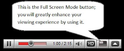
I think you'll like this... Same as the other one, use the Full Screen Mode, and no audio!
UPDATE: I've increased the size of the page, so I can now increase the size of the video. You may not need to watch in full screen mode anymore. Try it out.
UPDATE: I've increased the size of the page, so I can now increase the size of the video. You may not need to watch in full screen mode anymore. Try it out.
Friday, April 3, 2009
Civil 3D 2010 - Working with a Corridor
Autodesk has improved corridor modeling, and the enhancements great for productivity and useablity. Now, instead of guessing which region or baseline you are working with when in the corridor properties > parameters dialog box, you are given visual help. When a baseline is selected, the corresponding alignment will have thick red line over it. When a region is selected, it is outlined with a thick blue line. This may sound like a small update, but if you've ever designed an interesection traffic circle or anything that requires tweeking and going in and out of the parameters tab of corridor properties, you'll appriciate this. I'm trying the video thing with this post, no audio, but at least you can see moving pictures and I don't have to take and load 20 screenshots. Watch this video in Full Screen Mode. I'm still working on the best way to format these! See ya - Denver
Civil 3D Northing Easting Labels!!!!!!!!!!!
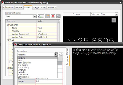
Yes! Civil 3D 2010 has northing/easting labels - without having to create a point!
The General notes now contain drop-down properties that contain Northing and Easting properties! Something so small, yet I'm so very excited. It's like when you're a kid and you get a old refrigerator box to play in. All of those expensive toys, but you'd rather play with the box. Maybe I'm revealing too much, maybe I was just a dumb kid!
I'll be posting more about Civil 3D 2010 in the coming days.
See ya,
Denver
Monday, March 30, 2009
Pre - 2010 Intersection Design with Civil 3D
**I'm working on the images, I've managed to screw a few of them up. Stay tuned!**
As we get ready to unviel Autodesk 2010 (AutoCAD, Civil 3D, Civil, Map 3D...), I thought I would tease those who have not heard about intersection design in Civil 3D 2010 with a hint that it's changing. Also, I don't want to forget how to create an intersection this way, so this is a great place to store this knowledge. Soak it in.
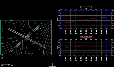
First, alignments and profiles are needed for centerline profiles. Proposed profiles need to be created for both main and side road(s). You'll also want to offset you're centerline alignments to your EOP distance. Then you can lay out the intersection geometry. You'll need the EOP lines for the curb returns in order to tie this whole thing together. If you've ever done this, you know that tieing it all together is much easier said than done much of the time.
Hopefully it's easy enough to see, but you'll have an assembly that consists of lanes only. This assembly will be applied through the intersection in the main road. The empty assembly will be used through the intersection on the side road(s).
The CR-L and CR-R assemblies will be used to tie the side road into the main road. Knowing how corridors work, hopefully you can see how the curb return alignments will play a role in carrying the curb return assemblies within the corridor.
A new baseline will need to be created for the side road. The first region will use the full assembly. The second region will use the empty assembly, the third region will be the full assembly, just like the main road. 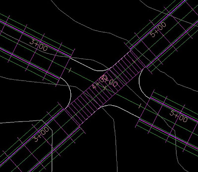 This should give you the image above - or a variation of it. As you can see, the curb return alignments will tie the side road into the main road. This is where you can use the existing corridor to help you out. Since you're tieing the side road into the main road, you'll want the curb return alignments to start at the point where they are touching the side road. See the image below for a better example.
 Notice that both curb return alignments' 0+00 station is at the end of the first region for the side road. The other side of the intersection will reflect a mirror of this, so that the 0+00 station is at the beginning of the third region of the side road. This will keep everything straight when you add the assemblies, it's easy to add the wrong assembly when dealing with curb returns. Also, you should name them as if you were looking down the street - the centerline alignment stationing will start at the beginning of the road. So, left is left, right is right, right? Left? What? Confused yet?
 Once that's done, you can start creating the curb return baselines and regions.
 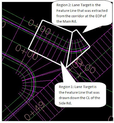 In the image above, I've added the left and right curb return baselines to the northwest side of the intersection. I'll need to do the same for the southeast side to complete the intersection.
Once that's done, so is the intersection - hopefully!
Stay tuned for a Civil 3D 2010 post explaining how intersection design is changing...
See ya,
Denver
As we get ready to unviel Autodesk 2010 (AutoCAD, Civil 3D, Civil, Map 3D...), I thought I would tease those who have not heard about intersection design in Civil 3D 2010 with a hint that it's changing. Also, I don't want to forget how to create an intersection this way, so this is a great place to store this knowledge. Soak it in.
First, alignments and profiles are needed for centerline profiles. Proposed profiles need to be created for both main and side road(s). You'll also want to offset you're centerline alignments to your EOP distance. Then you can lay out the intersection geometry. You'll need the EOP lines for the curb returns in order to tie this whole thing together. If you've ever done this, you know that tieing it all together is much easier said than done much of the time.
I'll usually trim the geometry to only what I need. If I won't need the EOP past where the curb returns start and end, I'll trim it out. Just to keep the drawing clean.
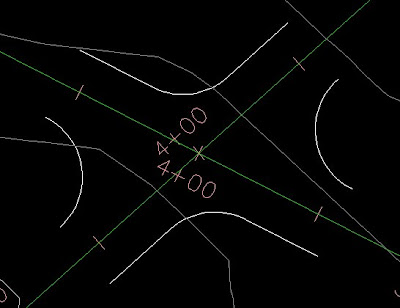
When the main road and side road(s) are perpendicular, things are a little easier. In this case, it's not. So the curb returns may need to be constructed of more than just arcs, you may need a tangent line in there to finish it out. The image below shows a close-up. You can see that the west and east side proposed curb returns are only arcs. The north and south sides are arcs with tangent lines connected to them. Since corridors can only project cross-sections perpendicular to the centerline, these tangent lines are needed to carry the curb return assembly into the next region.
An assembly will need to be created to start with. Maybe two if the main road and side road are different. From there, you'll need to create all of the assemblies you'll need to create the intersection.
Hopefully it's easy enough to see, but you'll have an assembly that consists of lanes only. This assembly will be applied through the intersection in the main road. The empty assembly will be used through the intersection on the side road(s).
The CR-L and CR-R assemblies will be used to tie the side road into the main road. Knowing how corridors work, hopefully you can see how the curb return alignments will play a role in carrying the curb return assemblies within the corridor.
For a basic intersection, this is all you should need to get started. You'll create the corridor using the full assembly for the first region of the main road. The second region should use the Thru Int assembly. The last region will use the Full assembly also.
A new baseline will need to be created for the side road. The first region will use the full assembly. The second region will use the empty assembly, the third region will be the full assembly, just like the main road.
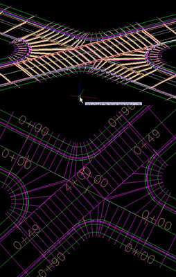
This should give you the image above - or a variation of it. As you can see, the curb return alignments will tie the side road into the main road. This is where you can use the existing corridor to help you out. Since you're tieing the side road into the main road, you'll want the curb return alignments to start at the point where they are touching the side road. See the image below for a better example.Notice that both curb return alignments' 0+00 station is at the end of the first region for the side road. The other side of the intersection will reflect a mirror of this, so that the 0+00 station is at the beginning of the third region of the side road. This will keep everything straight when you add the assemblies, it's easy to add the wrong assembly when dealing with curb returns. Also, you should name them as if you were looking down the street - the centerline alignment stationing will start at the beginning of the road. So, left is left, right is right, right? Left? What? Confused yet?At this point, you can create a surface from the corridor top links. The reason for this is to have an almost automatic transition from the side to the main road. You will create surface profiles of the corridor surface at each of the curb return alignments. You can then put these profiles into views to draw proposed profiles on top. It shouldn't be too difficult, just draw a straight line from the start to the end. See the image below for a few extra steps.

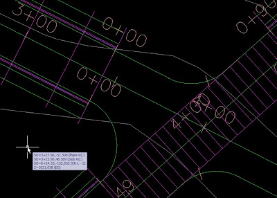
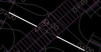
As mentioned in the image above, you'll want to draw a feature line from the EOP of the main road to where the region starts on the side road. You'll then assign corridor surface elevations to that feature line. It will be used to tie the lanes into the centerline. I've posted a picture below, the thick white lines represent the feature lines you'll need to draw.
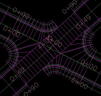
Once that's done, you can start creating the curb return baselines and regions.In the image above, I've added the left and right curb return baselines to the northwest side of the intersection. I'll need to do the same for the southeast side to complete the intersection.The image below shows a completed (almost) intersection. If this intersection had been perpendicular, it would be finished. But, since we had to use tangent lines to make all of the curb returns start and end perpendicular to it's opposite, we'll have to fill in those areas. You have to stop the second region where the actual curve meets the EOP since the assembly contains lanes. When the curve meets the EOP, all that is needed is the curb and gutter. The Main Rd. supplies the lanes at that point.
If another region is added, a new assembly can be applied. It would be exactly the same as the curb return assemblies, only no lanes would be attached.
Once that's done, so is the intersection - hopefully!
Stay tuned for a Civil 3D 2010 post explaining how intersection design is changing...
See ya,
Denver
Civil Design Job Openings...
I've come across a job opening for any Civil Design Professionals out there looking. I know first hand that this is a reputable company and a great place to work. They have two offices, one in Lincoln, the other in Omaha, NE. They are looking for a Sr. Civil Engineer and a Civil Tech. Here is their website, www.edc-civil.com.
Take a look at the job descriptions and email them if you like what you see. Good luck!
See ya,
Denver
Take a look at the job descriptions and email them if you like what you see. Good luck!
See ya,
Denver
Tuesday, March 10, 2009
Civil 3D Workflow
I've had a few questions over the past few months about workflows. Most recently, I've been questioned about Vault and Data Shortcuts. Well, Vault or Data Shortcuts go hand and hand with workflow methods. So what's recommended? That's a tough question that can't be answered without plenty of background questions and analysis.
If you're a one-man show or a 50 user office, the following workflow method can be effective when integrated into your current process. That's the key, successfully integrating the most effective workflow will save you time now and headaches later.
First, maybe you need to import raw survey data. No problem, right? Shouldn't be, when you install Civil 3D 2009 you have the option of installing the Survey Link. If you're a Land Desktop user, this is the same Survey Link from Land. You can also download add-ons from Trimble and Leica manufacturers. I've also found another program that will allow you to import just about any kind of survey data. If you read my Free Tools For Civil 3D post, you may already be familiar with CADDApps. If not, here's a link to their site for Civil 3D Tools. Check out Stringer Connect, it's free!
Maybe you have the raw data issue tackled. Many manufactures offer programs with their data collection instruments that will download the data. From there, you can probably use Survey Link to make a Fieldbook file if you've coded in linework or need to adjust point coordinates. If you just want to import your points into the drawing file, Civil 3D accepts a number of popular point file formats and even lets you create your own.
However you plan to get it done, once the Survey data has been inserted, managed and reduced, it's time to begin loading the drawing file with 3D models and linework and begin the design process.
It's here that the design workflow really begins. Always remember, the smaller the drawing size, the better it will perform. Also remember, Civil 3D is not Land Desktop (shouldn't be too hard). You should get used to xrefs, they can play a huge role in the data management process and Autodesk has left us with AutoCAD based tools to manage and manipulate them. DWF underlays are also a great way to keep drawing size down.
The main issue is how to manage the Civil 3D data that resides and bulks up your drawing. There are many different configurations, but first you must decide on Vault or Data Shortcuts. Breaking up the data should be the same either way, only minor differences in the actual interface of the workflow.
From this point forward, I'm going to use the term "data shortcut" when describing the act of exporting the data. If you're a Vault user, this is the same as adding a drawing to Vault or checking a drawing in that contains new Civil 3D data.
Once an existing surface is delivered, if not already done, a data shortcut should be created. It is a good idea to create a new drawing and create a reference to your existing surface in that drawing. Save it with only the surface and any background linework you might have. This way, when you need to start a new drawing with the surface in it, you won't have to keep recreating the reference, it's already there. You can apply that theory to any of your objects that you know you'll need references to in multiple files.
One general rule of thumb is if it needs to be be in more than one drawing file, create a shortcut for it so that it can be referenced into those files.
From there, some say that each alignment should be created in it's own drawing file. This is a good practice if multiple users will be creating alignments. I don't think this is practical for smaller scale firms and projects. In any event, create a data shortcut for all of the alignments that need to be shared.
Again, some say that you should create the existing profile within the same drawing that it's parent alignment was created in. This is based on the idea that each alignment was created in its own file. Again, this is a judgement call and either way, create a data shortcut for all of the profiles that need to be shared.
Proposed profiles can be created in the same file with the existing profile if desired, but could also be created in their own file(s). Create a shortcut for each proposed profile that needs to be shared.
If the corridor design is your next step, you're drawing will need the existing ground surface, baseline and target alignment(s), proposed profile(s), and any assemblies that will be needed. The alignments and profiles will be referenced into the drawing and the only hosted object(s) should be the assemblies.
After the corridor has been designed you may have new surfaces that were generated. They will need to have data shortcuts created so that they can be referenced into the next drawings. Depending on your situation, you could have a pipe network design to create next and you'll need alignments, profiles, and the corridor surfaces. To begin with, you're pipe network drawing has no hosted objects, only references.
You'll create data shortcuts for all of your pipe networks that need to be shared and might move on to create cross sections. Cross sections drawings will need to contain all the data that is required to be shown within the plotted cross section views. Cross section creation requires an alignment at least, so you know alignments will need to be referenced, any surfaces and pipe networks should be referenced also. The corridor is one object that is typically shown within cross section views but corridors cannot be referenced with Vault or Data Shortcuts. So do you have to start with the original corridor drawing?
Corridors can be xref'd into cross section drawings. Xref's don't work if you're trying to sample surface or pipe network data, but corridors can be sampled through xrefs - and they should be.
Whew! That's a windy post. I've thrown a lot out there in this post, I hope it's helpful to you. I won't get into plan and profile sheets this time, not to mention Sheet Set Manager... I'm open to questions and comments if anybody has them, good luck!
See ya,
Denver
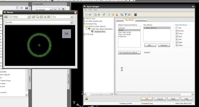
Multi-View Blocks
A multi-view block is a block that multiple views, duh! They are packed inside of the AutoCAD DVD and install inside of the Sample directory when you install AutoCAD.
For Civil 3D users, this means an easy way to quickly insert objects that will allow you to better visualize your design. You can even automate this further by using multi-view blocks as point symbols.
For example, your tree symbol may look the like the image on the left in the plan view, but when the model is rotated in 3D space, you’ll get the image on the right automatically.
 Trees aren’t the only objects available out of the box either. Autodesk supplies many types of symbols as multi-view blocks. Houses, traffic signs, light poles, and much more. You can also create multi-view block definitions. Unfortunately, AutoCAD itself does not support creation of multi-view blocks, but you can insert and use them. Vertical applications like Civil 3D and Architecture support creation, so how do you create them?
MVBLOCK – that’s the command you’ll enter define a multi-view block. Before you can define the block though, you’ll need all views inserted into the drawing, or at least a drawing that you can access. The Style manager helps you keep track of the blocks you’ve collected as multi-views.
Remember, once you define a multi-view block, you can carry it anywhere – just like a regular block. Explore multi-view blocks and the style manager, they can be powerful tools.
Civil 3D 2009 Update 2.1 Now Available
Autodesk has released the next service pack, now called Update for Civil 3D 2009, 2.1 is available and can be downloaded from the Autodesk website here.
Please report any bugs to Autodesk using the Customer Error Reporting System!! And as always, actually READ the README file. It's practacly screaming at you!
See ya,
Denver
Please report any bugs to Autodesk using the Customer Error Reporting System!! And as always, actually READ the README file. It's practacly screaming at you!
See ya,
Denver
Friday, January 23, 2009
Civil 3D Update 2
DO NOT INSTALL...
If you've downloaded Civil 3D 2009 Update 2 or Service Pack 2, don't install it. If you've installed it, uninstall it. To uninstall, go to Add/Remove Programs and check the "Show Updates" checkbox at the top of the dialog box to see all updates installed. You can uninstall them this way.
Update 2 has some nice fixes included, but it breaks E-Transmitt functionality. It also causes Civil 3D to not write external surface files. This means if you create a large surface, and Civil 3D has to write an external file to manage it, that file doesn't get written. So you're suface is gone the next time you open the file!
I hope nobody has had any trouble with it, if so, uninstall!!
See ya,
Denver
Wednesday, January 7, 2009
BIM and Civil 3D
Happy New Year! Here's hoping 2009 is a great year!
I think it's appropriate to start the year off with a topic that I'm sure will on everbody's mind this year. BIM, otherwise known as Building Information Modeling is technology that is quickly moving to the forefront of the design world. But how does it translate to civil engineers?Well, BIM isn't just for architects, in fact, it's for everyone involved in the design of anything that will be built. That goes for buildings, bridges, roads, even parking lots. Try not to think of the "building" part as an actual building, rather the act of building.
BIM is extremely useful when multiple disciplines are involved in the same project. Imagine having an architect share his CAD building with the civil engineer who is designing the parking lot or planning the land layout for drainage. The building can be loaded into the topo and shown in it's future real world location for design. Now if the architect needs to make changes, he has the future topo design to aid him when making revisions to the building.
Autodesk Revit Architecture and AutoCAD Civil 3D can interchange models today, that functionality is already present. I hope we see more interoperability between these two powerful programs in the near future. Plus, Autodesk NavisWorks is compatible with both products, so models can be loaded to NavisWorks for even more analysis. All of this is going on before the site is even disturbed.
If NavisWorks was a foreign word to you, check it out at the Autodesk website here.
Are you getting the idea yet? BIM allows engineers, architects, and planners the ability to build it (whatever "it" is) before "it's" built. Intelligent models are giving us the ability to detect design flaws before the plans go out for construction. BIM reduces design time, field revisions, and can significantly reduce build time and cost.
It doesn't stop there, though. For civil engineers, BIM also means machine control and automation. This is exciting technology, true Feild to Finish technology! A number of survey manufacturers have put their hat in the ring and developed these next-generation grading systems.
Here's a link to Trimble:
http://www.trimble.com/GCS900.shtml
And Leica...
http://www.leica-geosystems.com/corporate/en/lgs_70038.htm
I've pasted an image of the Leica reciever for their PowerGrade 3D system below. Hopefully BIM makes a little more sense to you now. I'm open to comments if anyone has anything to contribute!
See ya - Denver
Subscribe to:
Comments (Atom)