As we get ready to unviel Autodesk 2010 (AutoCAD, Civil 3D, Civil, Map 3D...), I thought I would tease those who have not heard about intersection design in Civil 3D 2010 with a hint that it's changing. Also, I don't want to forget how to create an intersection this way, so this is a great place to store this knowledge. Soak it in.
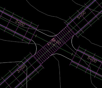
First, alignments and profiles are needed for centerline profiles. Proposed profiles need to be created for both main and side road(s). You'll also want to offset you're centerline alignments to your EOP distance. Then you can lay out the intersection geometry. You'll need the EOP lines for the curb returns in order to tie this whole thing together. If you've ever done this, you know that tieing it all together is much easier said than done much of the time.
I'll usually trim the geometry to only what I need. If I won't need the EOP past where the curb returns start and end, I'll trim it out. Just to keep the drawing clean.
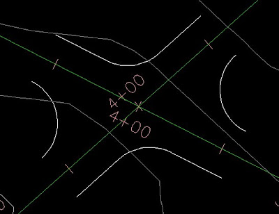
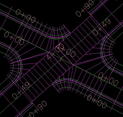
When the main road and side road(s) are perpendicular, things are a little easier. In this case, it's not. So the curb returns may need to be constructed of more than just arcs, you may need a tangent line in there to finish it out. The image below shows a close-up. You can see that the west and east side proposed curb returns are only arcs. The north and south sides are arcs with tangent lines connected to them. Since corridors can only project cross-sections perpendicular to the centerline, these tangent lines are needed to carry the curb return assembly into the next region.
An assembly will need to be created to start with. Maybe two if the main road and side road are different. From there, you'll need to create all of the assemblies you'll need to create the intersection.
Hopefully it's easy enough to see, but you'll have an assembly that consists of lanes only. This assembly will be applied through the intersection in the main road. The empty assembly will be used through the intersection on the side road(s).
The CR-L and CR-R assemblies will be used to tie the side road into the main road. Knowing how corridors work, hopefully you can see how the curb return alignments will play a role in carrying the curb return assemblies within the corridor.
For a basic intersection, this is all you should need to get started. You'll create the corridor using the full assembly for the first region of the main road. The second region should use the Thru Int assembly. The last region will use the Full assembly also.
A new baseline will need to be created for the side road. The first region will use the full assembly. The second region will use the empty assembly, the third region will be the full assembly, just like the main road.
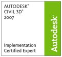
 This should give you the image above - or a variation of it. As you can see, the curb return alignments will tie the side road into the main road. This is where you can use the existing corridor to help you out. Since you're tieing the side road into the main road, you'll want the curb return alignments to start at the point where they are touching the side road. See the image below for a better example.
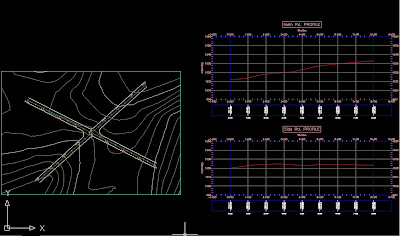
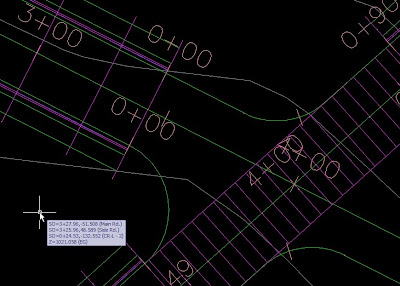 Notice that both curb return alignments' 0+00 station is at the end of the first region for the side road. The other side of the intersection will reflect a mirror of this, so that the 0+00 station is at the beginning of the third region of the side road. This will keep everything straight when you add the assemblies, it's easy to add the wrong assembly when dealing with curb returns. Also, you should name them as if you were looking down the street - the centerline alignment stationing will start at the beginning of the road. So, left is left, right is right, right? Left? What? Confused yet?
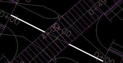
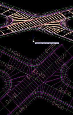
At this point, you can create a surface from the corridor top links. The reason for this is to have an almost automatic transition from the side to the main road. You will create surface profiles of the corridor surface at each of the curb return alignments. You can then put these profiles into views to draw proposed profiles on top. It shouldn't be too difficult, just draw a straight line from the start to the end. See the image below for a few extra steps.

As mentioned in the image above, you'll want to draw a feature line from the EOP of the main road to where the region starts on the side road. You'll then assign corridor surface elevations to that feature line. It will be used to tie the lanes into the centerline. I've posted a picture below, the thick white lines represent the feature lines you'll need to draw.
 Once that's done, you can start creating the curb return baselines and regions.
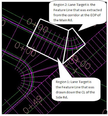 In the image above, I've added the left and right curb return baselines to the northwest side of the intersection. I'll need to do the same for the southeast side to complete the intersection.
The image below shows a completed (almost) intersection. If this intersection had been perpendicular, it would be finished. But, since we had to use tangent lines to make all of the curb returns start and end perpendicular to it's opposite, we'll have to fill in those areas. You have to stop the second region where the actual curve meets the EOP since the assembly contains lanes. When the curve meets the EOP, all that is needed is the curb and gutter. The Main Rd. supplies the lanes at that point.
If another region is added, a new assembly can be applied. It would be exactly the same as the curb return assemblies, only no lanes would be attached.
Once that's done, so is the intersection - hopefully!
Stay tuned for a Civil 3D 2010 post explaining how intersection design is changing...
See ya,
Denver
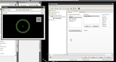
 Trees aren’t the only objects available out of the box either. Autodesk supplies many types of symbols as multi-view blocks. Houses, traffic signs, light poles, and much more. You can also create multi-view block definitions. Unfortunately, AutoCAD itself does not support creation of multi-view blocks, but you can insert and use them. Vertical applications like Civil 3D and Architecture support creation, so how do you create them?