That led me to think of other ways to create linetypes and as I was cleaning out my overpopulated "in/out" box in my office, I came across a piece of paper that I've had for many years describing how to open up notepad and generate a linetype file that AutoCAD will read. I thought that I would just get rid of the paper since it's old and newer, quicker ways of linetype generation are available. Then I thought, maybe I'll put it on my blog, so here we are. After I transcribe this, I'll finally be able to get rid of that paper that has been following me around for years!
If you open the ACAD.LIN file that ships with AutoCAD, you'll see all of the linetype descriptions and their definitions. This is a general linetype you will see in ACAD.LIN;
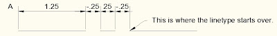
*CENTER,Center ____ _ ____ _ ____ _ ____ _ ____ _ ____
A,1.25,-.25,.25,-.25
The top line always starts with an astrik followed by the name of the linteype. The description is next, seperated from the name with a comma. After the description, a preview of the linetype is shown.
The bottom line is the linetype definition. The definition always begins with a capitol A. Next is the length of the first dash (1.25). AutoCAD linetypes must start with a dash. There is no way around it. Next is the location of smaller dash from the left side of the longer dash (-.25). Next is the length of the smaller dash (.25). The last value is the location of the smaller dash from the right side of the longer dash (-.25). All of those different values are seperated with a comma.
That is a simple linetype definition. What if you need to add text or symbols to your linetype? Easy enough, let's take a look.
*GAS_LINE,Gas line ----GAS----GAS----GAS----GAS----GAS----GAS--A,.5,-.2,["GAS",STANDARD,S=.1,R=0.0,X=-0.1,Y=-.05],-.25
There are a few more items to consider within the definition above. The top line is the same and the beginning of the bottom line is the same. First the A. Then the length of the first dash. Then the distance of the text from the left side of the first dash. Then, within the brackets, the text to be shown is listed in quotes followed by the text style ("GAS",Standard). The S= stands for Size of Text, followed by the text size value (S=.1). Then R= (Rotation) followed by the rotation value (R=0.0). Then X= (Location of text from the right side of the dash) followed by the value (X=-.05). Then Y= (Location of the text above or below the dash) followed by the value (Y=-.05). If a negative value is used, the text is moved down, below the dash. This rounds out the bracket text. The final value is the location of the text from the right side of the dash (-.25). Again, this is all seperated by commas.
I don't know that there is enough space to get a full drawing description like I've pasted below the simple linetype. You can download a PDF of these linetype instructions here.
There are a number of options for creating linetypes within AutoCAD. This is just one of them, and it's the long (old) way at that!
See ya,
Denver


1 comment:
Hi
Nice Blog
Civil CAD Courses in Coimbatore
Post a Comment