I've come across a job opening for any Civil Design Professionals out there looking. I know first hand that this is a reputable company and a great place to work. They have two offices, one in Lincoln, the other in Omaha, NE. They are looking for a Sr. Civil Engineer and a Civil Tech. Here is their website, www.edc-civil.com.
Take a look at the job descriptions and email them if you like what you see. Good luck!
See ya,
Denver
Monday, March 30, 2009


Tuesday, March 10, 2009
Civil 3D Workflow
I've had a few questions over the past few months about workflows. Most recently, I've been questioned about Vault and Data Shortcuts. Well, Vault or Data Shortcuts go hand and hand with workflow methods. So what's recommended? That's a tough question that can't be answered without plenty of background questions and analysis.
If you're a one-man show or a 50 user office, the following workflow method can be effective when integrated into your current process. That's the key, successfully integrating the most effective workflow will save you time now and headaches later.
First, maybe you need to import raw survey data. No problem, right? Shouldn't be, when you install Civil 3D 2009 you have the option of installing the Survey Link. If you're a Land Desktop user, this is the same Survey Link from Land. You can also download add-ons from Trimble and Leica manufacturers. I've also found another program that will allow you to import just about any kind of survey data. If you read my Free Tools For Civil 3D post, you may already be familiar with CADDApps. If not, here's a link to their site for Civil 3D Tools. Check out Stringer Connect, it's free!
Maybe you have the raw data issue tackled. Many manufactures offer programs with their data collection instruments that will download the data. From there, you can probably use Survey Link to make a Fieldbook file if you've coded in linework or need to adjust point coordinates. If you just want to import your points into the drawing file, Civil 3D accepts a number of popular point file formats and even lets you create your own.
However you plan to get it done, once the Survey data has been inserted, managed and reduced, it's time to begin loading the drawing file with 3D models and linework and begin the design process.
It's here that the design workflow really begins. Always remember, the smaller the drawing size, the better it will perform. Also remember, Civil 3D is not Land Desktop (shouldn't be too hard). You should get used to xrefs, they can play a huge role in the data management process and Autodesk has left us with AutoCAD based tools to manage and manipulate them. DWF underlays are also a great way to keep drawing size down.
The main issue is how to manage the Civil 3D data that resides and bulks up your drawing. There are many different configurations, but first you must decide on Vault or Data Shortcuts. Breaking up the data should be the same either way, only minor differences in the actual interface of the workflow.
From this point forward, I'm going to use the term "data shortcut" when describing the act of exporting the data. If you're a Vault user, this is the same as adding a drawing to Vault or checking a drawing in that contains new Civil 3D data.
Once an existing surface is delivered, if not already done, a data shortcut should be created. It is a good idea to create a new drawing and create a reference to your existing surface in that drawing. Save it with only the surface and any background linework you might have. This way, when you need to start a new drawing with the surface in it, you won't have to keep recreating the reference, it's already there. You can apply that theory to any of your objects that you know you'll need references to in multiple files.
One general rule of thumb is if it needs to be be in more than one drawing file, create a shortcut for it so that it can be referenced into those files.
From there, some say that each alignment should be created in it's own drawing file. This is a good practice if multiple users will be creating alignments. I don't think this is practical for smaller scale firms and projects. In any event, create a data shortcut for all of the alignments that need to be shared.
Again, some say that you should create the existing profile within the same drawing that it's parent alignment was created in. This is based on the idea that each alignment was created in its own file. Again, this is a judgement call and either way, create a data shortcut for all of the profiles that need to be shared.
Proposed profiles can be created in the same file with the existing profile if desired, but could also be created in their own file(s). Create a shortcut for each proposed profile that needs to be shared.
If the corridor design is your next step, you're drawing will need the existing ground surface, baseline and target alignment(s), proposed profile(s), and any assemblies that will be needed. The alignments and profiles will be referenced into the drawing and the only hosted object(s) should be the assemblies.
After the corridor has been designed you may have new surfaces that were generated. They will need to have data shortcuts created so that they can be referenced into the next drawings. Depending on your situation, you could have a pipe network design to create next and you'll need alignments, profiles, and the corridor surfaces. To begin with, you're pipe network drawing has no hosted objects, only references.
You'll create data shortcuts for all of your pipe networks that need to be shared and might move on to create cross sections. Cross sections drawings will need to contain all the data that is required to be shown within the plotted cross section views. Cross section creation requires an alignment at least, so you know alignments will need to be referenced, any surfaces and pipe networks should be referenced also. The corridor is one object that is typically shown within cross section views but corridors cannot be referenced with Vault or Data Shortcuts. So do you have to start with the original corridor drawing?
Corridors can be xref'd into cross section drawings. Xref's don't work if you're trying to sample surface or pipe network data, but corridors can be sampled through xrefs - and they should be.
Whew! That's a windy post. I've thrown a lot out there in this post, I hope it's helpful to you. I won't get into plan and profile sheets this time, not to mention Sheet Set Manager... I'm open to questions and comments if anybody has them, good luck!
See ya,
Denver
If you're a one-man show or a 50 user office, the following workflow method can be effective when integrated into your current process. That's the key, successfully integrating the most effective workflow will save you time now and headaches later.
First, maybe you need to import raw survey data. No problem, right? Shouldn't be, when you install Civil 3D 2009 you have the option of installing the Survey Link. If you're a Land Desktop user, this is the same Survey Link from Land. You can also download add-ons from Trimble and Leica manufacturers. I've also found another program that will allow you to import just about any kind of survey data. If you read my Free Tools For Civil 3D post, you may already be familiar with CADDApps. If not, here's a link to their site for Civil 3D Tools. Check out Stringer Connect, it's free!
Maybe you have the raw data issue tackled. Many manufactures offer programs with their data collection instruments that will download the data. From there, you can probably use Survey Link to make a Fieldbook file if you've coded in linework or need to adjust point coordinates. If you just want to import your points into the drawing file, Civil 3D accepts a number of popular point file formats and even lets you create your own.
However you plan to get it done, once the Survey data has been inserted, managed and reduced, it's time to begin loading the drawing file with 3D models and linework and begin the design process.
It's here that the design workflow really begins. Always remember, the smaller the drawing size, the better it will perform. Also remember, Civil 3D is not Land Desktop (shouldn't be too hard). You should get used to xrefs, they can play a huge role in the data management process and Autodesk has left us with AutoCAD based tools to manage and manipulate them. DWF underlays are also a great way to keep drawing size down.
The main issue is how to manage the Civil 3D data that resides and bulks up your drawing. There are many different configurations, but first you must decide on Vault or Data Shortcuts. Breaking up the data should be the same either way, only minor differences in the actual interface of the workflow.
From this point forward, I'm going to use the term "data shortcut" when describing the act of exporting the data. If you're a Vault user, this is the same as adding a drawing to Vault or checking a drawing in that contains new Civil 3D data.
Once an existing surface is delivered, if not already done, a data shortcut should be created. It is a good idea to create a new drawing and create a reference to your existing surface in that drawing. Save it with only the surface and any background linework you might have. This way, when you need to start a new drawing with the surface in it, you won't have to keep recreating the reference, it's already there. You can apply that theory to any of your objects that you know you'll need references to in multiple files.
One general rule of thumb is if it needs to be be in more than one drawing file, create a shortcut for it so that it can be referenced into those files.
From there, some say that each alignment should be created in it's own drawing file. This is a good practice if multiple users will be creating alignments. I don't think this is practical for smaller scale firms and projects. In any event, create a data shortcut for all of the alignments that need to be shared.
Again, some say that you should create the existing profile within the same drawing that it's parent alignment was created in. This is based on the idea that each alignment was created in its own file. Again, this is a judgement call and either way, create a data shortcut for all of the profiles that need to be shared.
Proposed profiles can be created in the same file with the existing profile if desired, but could also be created in their own file(s). Create a shortcut for each proposed profile that needs to be shared.
If the corridor design is your next step, you're drawing will need the existing ground surface, baseline and target alignment(s), proposed profile(s), and any assemblies that will be needed. The alignments and profiles will be referenced into the drawing and the only hosted object(s) should be the assemblies.
After the corridor has been designed you may have new surfaces that were generated. They will need to have data shortcuts created so that they can be referenced into the next drawings. Depending on your situation, you could have a pipe network design to create next and you'll need alignments, profiles, and the corridor surfaces. To begin with, you're pipe network drawing has no hosted objects, only references.
You'll create data shortcuts for all of your pipe networks that need to be shared and might move on to create cross sections. Cross sections drawings will need to contain all the data that is required to be shown within the plotted cross section views. Cross section creation requires an alignment at least, so you know alignments will need to be referenced, any surfaces and pipe networks should be referenced also. The corridor is one object that is typically shown within cross section views but corridors cannot be referenced with Vault or Data Shortcuts. So do you have to start with the original corridor drawing?
Corridors can be xref'd into cross section drawings. Xref's don't work if you're trying to sample surface or pipe network data, but corridors can be sampled through xrefs - and they should be.
Whew! That's a windy post. I've thrown a lot out there in this post, I hope it's helpful to you. I won't get into plan and profile sheets this time, not to mention Sheet Set Manager... I'm open to questions and comments if anybody has them, good luck!
See ya,
Denver
Multi-View Blocks
A multi-view block is a block that multiple views, duh! They are packed inside of the AutoCAD DVD and install inside of the Sample directory when you install AutoCAD.
For Civil 3D users, this means an easy way to quickly insert objects that will allow you to better visualize your design. You can even automate this further by using multi-view blocks as point symbols.
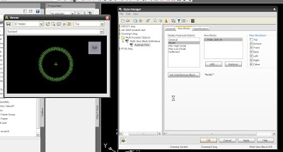
For example, your tree symbol may look the like the image on the left in the plan view, but when the model is rotated in 3D space, you’ll get the image on the right automatically.
For Civil 3D users, this means an easy way to quickly insert objects that will allow you to better visualize your design. You can even automate this further by using multi-view blocks as point symbols.
For example, your tree symbol may look the like the image on the left in the plan view, but when the model is rotated in 3D space, you’ll get the image on the right automatically.
 Trees aren’t the only objects available out of the box either. Autodesk supplies many types of symbols as multi-view blocks. Houses, traffic signs, light poles, and much more. You can also create multi-view block definitions. Unfortunately, AutoCAD itself does not support creation of multi-view blocks, but you can insert and use them. Vertical applications like Civil 3D and Architecture support creation, so how do you create them?
MVBLOCK – that’s the command you’ll enter define a multi-view block. Before you can define the block though, you’ll need all views inserted into the drawing, or at least a drawing that you can access. The Style manager helps you keep track of the blocks you’ve collected as multi-views.
Remember, once you define a multi-view block, you can carry it anywhere – just like a regular block. Explore multi-view blocks and the style manager, they can be powerful tools.
Civil 3D 2009 Update 2.1 Now Available
Autodesk has released the next service pack, now called Update for Civil 3D 2009, 2.1 is available and can be downloaded from the Autodesk website here.
Please report any bugs to Autodesk using the Customer Error Reporting System!! And as always, actually READ the README file. It's practacly screaming at you!
See ya,
Denver
Please report any bugs to Autodesk using the Customer Error Reporting System!! And as always, actually READ the README file. It's practacly screaming at you!
See ya,
Denver
Friday, January 23, 2009
Civil 3D Update 2
DO NOT INSTALL...
If you've downloaded Civil 3D 2009 Update 2 or Service Pack 2, don't install it. If you've installed it, uninstall it. To uninstall, go to Add/Remove Programs and check the "Show Updates" checkbox at the top of the dialog box to see all updates installed. You can uninstall them this way.
Update 2 has some nice fixes included, but it breaks E-Transmitt functionality. It also causes Civil 3D to not write external surface files. This means if you create a large surface, and Civil 3D has to write an external file to manage it, that file doesn't get written. So you're suface is gone the next time you open the file!
I hope nobody has had any trouble with it, if so, uninstall!!
See ya,
Denver
If you've downloaded Civil 3D 2009 Update 2 or Service Pack 2, don't install it. If you've installed it, uninstall it. To uninstall, go to Add/Remove Programs and check the "Show Updates" checkbox at the top of the dialog box to see all updates installed. You can uninstall them this way.
Update 2 has some nice fixes included, but it breaks E-Transmitt functionality. It also causes Civil 3D to not write external surface files. This means if you create a large surface, and Civil 3D has to write an external file to manage it, that file doesn't get written. So you're suface is gone the next time you open the file!
I hope nobody has had any trouble with it, if so, uninstall!!
See ya,
Denver
Subscribe to:
Posts (Atom)

 Posts
Posts